Features
Secure Boot
The firmware component of TRS unconditionally enables UEFI secure boot for all supported platforms. There are some hardware requirements that will dictate how Secure Boot is configured and enabled on your hardware.
[UEFI] (§ 32.3.6 Platform Firmware Key Storage Requirements) defines that the Platform and Key exchange keys must be stored in a non-volatile storage which is tamper protected.
On Arm servers this is usually tackled by having a dedicated flash which is only accessible by the secure world.
Hardware which was designed with security in mind has the following options.
Hardware |
UEFI Secure Boot |
Measured Boot |
|---|---|---|
RPMB 1 |
x |
x |
Discrete TPM |
x |
|
Flash in secure world |
x |
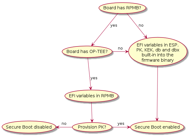
The reality on embedded boards is different though. In the embedded case, we don’t have a dedicated flash. What’s becoming more common though is eMMC devices with an RPMB partition.
If the board has a RPMB and OP-TEE support, Trusted Substrate will use that device to store all the EFI variables.

However for boards that don’t have an RPMB the UEFI public keys (PK, KEK, DB etc) are built-in into the firmware binary. Bundling those keys comes with it’s own set of limitations. The most notable ones being that in order to update any security related EFI variable, you need to update the bootloader and you can only boot signed binaries by default. Other, non security critical, EFI variables are stored in a file located in the ESP.
- 1
Requires OP-TEE support and a way to program the RPMB with a unique per hardware key (e.g a fuse accessible only from the secure world). Setting EFI variables at runtime (from the OS) not supported
Hardware and UEFI variable limitations
The firmware automatically enables and disables UEFI Secure Boot based on the existence of the Platform Key (PK). As a consequence boards that embed the keys in the firmware binary will only be allowed to boot signed binaries and you won’t be able to change the UEFI keys. See Building with your own certificates
On the other hand boards that store the variables in the RPMB come with an empty PK and the user must provision one during the setup process in order to enable Secure Boot.
Measured Boot
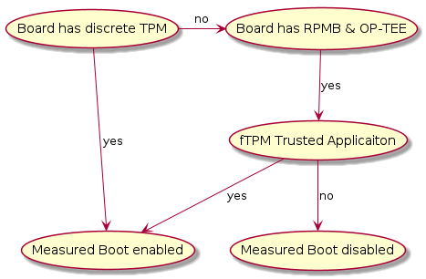
TRS is designed to take advantage of Trusted Platform modules. The firmware part of TRS supports the EFI TCG Protocol as well as TCG PC Client Specific Platform Firmware Profile Specification and provides the building blocks the OS needs for measured boot.
During the OS first boot it will automatically scan for a TPM. If such a device is present it will generate a random key, encrypt the root filesystem and seal it against measurements found in PCR7 which holds the Secure Boot Policy and EFI keys used for UEFI Secure Boot.
Trusted Platform module
TPMs are microcontrollers designed for cryptographic tasks. They contain a set of Platform Configuration Registers (PCRs) which are used to measure the system configuration and software.
PCRs start zeroed out and can only reset with a system reboot. Those can be extended by writing a SHA hash (typically SHA-1/256/384/512 for TPMv2) into the PCR. To store a new value in a PCR, the existing value is extended with a new value as follows: PCR[N] = HASHalg( PCR[N] || ArgumentOfExtend )
Trusted Substrate is designed to work with either discrete TPMs or provide an [fTPM] running in OP-TEE.
LUKS2 disk encryption
If a TPM is present on the device TRS will automatically detect it, generate a random password on first boot, seal it against PCR7 and encrypt your root filesystem using aes-xts-plain.
TRS is designed to work regardless of the TPM implementation. We support devices with a discrete TPM, an [fTPM] or for QEMU a [SWTPM]
LUKS2 Encryption

LUKS2 Decryption

OP-TEE OS
OP-TEE is our Secure World OS of choice in TRS. We use it for a number of reasons with the most notable ones being
Run [fTPM] is the hardware doesn’t have a discrete TPM.
Store EFI variables on boards that have an RPMB.
Provide a DRBG if the hardware doesn’t provide a TRNG.
Provide a PKCS#11 provider to PARSEC.
Conceptually the components interacting with OP-TEE in the TRS build can be seen
in the image below. The Features lane there indicates which exceptions
levels are involved in a certain use case. For example, “TEE: Secure Storage”
is all kept in (S)EL-0 and (S)EL-1.

Note that this image is rather generic as depicted here. We have other areas
that could (and should) be added as well, for example SCMI, Xen,
FF-A, SwTPM to name a few. But perhaps it’s better to add them as
separate diagrams to avoid making the images too complex.