Features
The purpose of this page is to provide an overview of the essential features of the Trusted Reference Stack (TRS), including it communication capabilities with internal and external system components. This information aims to help readers understand what TRS can offer in terms of its functionality and interoperability.
TRS features
Secure Boot
The firmware component of TRS unconditionally enables UEFI secure boot for all supported platforms. There are some hardware requirements that will dictate how Secure Boot is configured and enabled on your hardware. [UEFI] (section 32.3.6 Platform Firmware Key Storage Requirements) specifies that the Platform (PK) and Key Exchange Keys (KEK) must be stored in tamper-resistant nonvolatile storage. On Arm servers this is usually tackled by having a dedicated flash which is only accessible by the secure world. Below is a table describing the security features enabled by various hardware entities.
Hardware |
UEFI Secure Boot |
Measured Boot |
|---|---|---|
RPMB [1] |
x |
x |
Discrete TPM |
x |
|
Flash in secure world |
x |
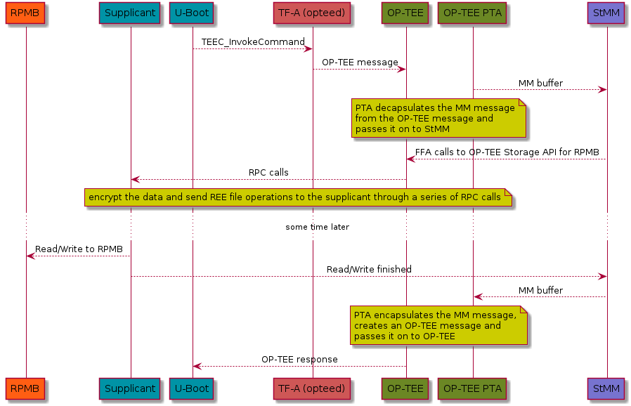
In the embedded case, we typically don’t have a dedicated flash. What’s becoming more common though is eMMC storage devices with an RPMB partition. The eMMC storage devices are solid-state storage devices that leverage flash memory technology to provide affordable and reliable storage for small electronic devices. The eMMC device’s RPMB partition (Replay Protected Memory Block) provides a secure storage area for sensitive data using a replay protection mechanism to prevent unauthorized access and modification. Because of this, the eMMC devices has become a key component for numerous electronic devices, serving as dependable and secure data storage. Trusted Substrate will use that RPMB partition to store all the EFI variables, if the device runs OP-TEE and have a RPMB partition.
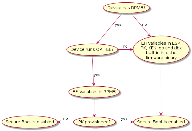
For devices without an RPMB, the UEFI public keys (PK, KEK, DB, etc.) will be embedded in the firmware binary. The wrapping of these keys has its own limitations and consequences. You have to make sure that the public keys are immutable, something that is typically done by tying them to the Root of Trust (ROT). To update any security-related EFI variables, you must update the firmware. By default, you can only run binaries that have been digitally signed. Other EFI variables that are not security-critical are stored in a file within the ESP.
On the sequence diagram below, we see a typical scenario, describing the different components involved when storing and retrieving data from a RPMB partition.
Secure boot limitations
The firmware automatically enables and disables UEFI Secure Boot based on the existence of the Platform Key (PK). As a consequence, devices that embed keys into the firmware binary will only be allowed to boot signed binaries and you won’t be able to change the UEFI keys. See Building with your own certificates. On the other hand, devices that stores the variables in the RPMB come with an uninitialized PK. As such the user must provide a PK during the setup process in order to enable Secure Boot. The diagram below illustrates how a device can be set up to have secure boot enabled or disabled.
Measured Boot
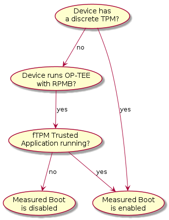
TRS has been designed to take advantage of TPM devices. The firmware part of TRS supports the EFI TCG Protocol as well as TCG PC Client Specific Platform Firmware Profile Specification and provides the building blocks the OS needs for measured boot. During the first OS boot, it will automatically look for a TPM device. If such a TPM device is present it will generate a random key, encrypt the root filesystem and seal it against measurements found in PCR7 which holds the Secure Boot Policy and EFI keys used for UEFI Secure Boot. Trusted Substrate supports discrete TPMs as well as firmware based TPMs. Which one being used depends on the device capabilities and the software available. The diagram below illustrates how a device ends up running with measured boot enabled or disabled.
Authenticated Capsule Updates
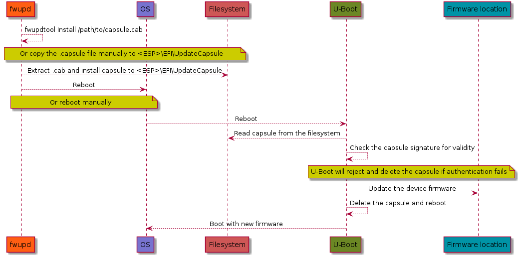
TRS can update the device firmware using Authenticated capsule updates on-disk A more detailed explanation is included in our Updating the firmware chapter, but the sequence diagram that follows should provide enough information on how the firmware is updated.
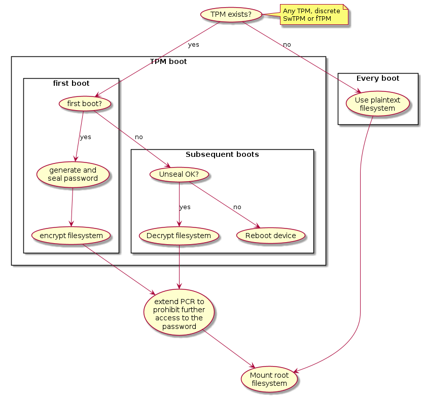
Disk encryption
The TRS build is by default configured to look for a TPM device. If it does, it
will generate a random password during the first boot, seal (see TPM sealing)
it against PCR7 which is the PCR meant to be used for the secure boot state.
Using this password, it will encrypt your root filesystem using
aes-xts-plain algorithm and block mode. This is something that will happen
regardless of TPM implementation. If on the other hand there is no TPM
available, then the devices will use a plaintext/unencrypted filesystem. This is
all explained in the graph below, where you can follow the steps from booting up
the device to the filesystem being mounted.
Important
The encryption here will start from U-Boot, i.e, in TRS it’s currently U-Boot that is the first component leveraging the TPM device. This is something that might change in the future.
It’s also worth to pay attention to the step that extends the PCR once more to prohibit access to the password.
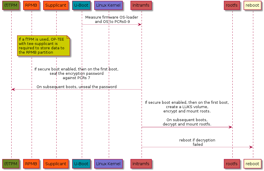
To get an idea of the components involved, please have a look at the sequence diagram below showing the call flow between the components involved when setting up disk encryption in TRS using a TPM device.
Virtualization
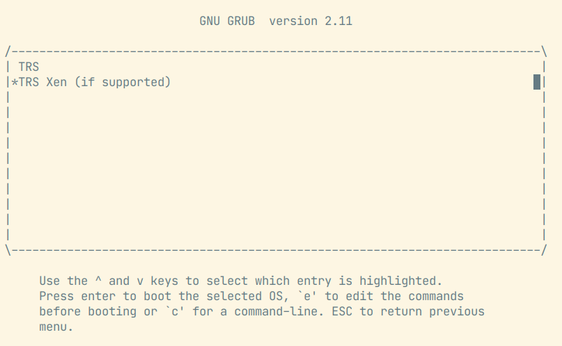
So far, TRS uses Xen as the Hypervisor for Virtualization use cases. When Xen is
enabled, the GRUB menu provides an entry TRS Xen (if supported) making it
possible to boot the Xen hypervisor. What you will see is something similar to
the image below.
Xen hypervisors’ EFI program and configuration file (xen.cfg) both are
located in the root folder of boot partition. The configuration file contains
settings for Xens’ log levels when it comes debugging, it also contains the path
to the Linux kernel image, the Linux kernel command line, etc. The Xen
hypervisor parses the configuration file and boots Linux kernel image.
Note, the Xen hypervisor doesn’t load initial ramdisk, this is different from the boot flow in bare metal mode which loads both the initial ramdisk as well as the Linux kernel image.
# SPDX-License-Identifier: MIT

[global]
default=xen

[xen]
options=noreboot dom0_mem=4096M bootscrub=0 iommu=on loglvl=error guest_loglvl=error
kernel=Image console=hvc0 earlycon=xenboot rootwait root=PARTUUID=f3374295-b635-44af-90b6-3f65ded2e2e4
After a booting up the system successfully, we can use the command xl list
to list Xen domains. The Xen Dom0 with naming Domain-0 is created by
default and it will look like this:
root@trs-qemuarm64:~# xl list
Name                                        ID   Mem VCPUs      State   Time(s)
Domain-0                                     0  4096    32     r-----      63.2
The goal of TRS is to support both Dom0 and DomU with the same root
filesystem image. However, if Xen Dom0 automatically boot up Xen DomU
from the root filesystem, Xen DomU will automatically boot the next level’s
Xen DomU, and so on, causing a nesting issue. For this reason, the TRS root
file system does not contain anything for Xen DomU. To deploy a virtual
machine for Xen DomU, the procedures outlined below must be followed.
Firstly, you need to create a virtual machine configuration file
ewaol-guest-vm1.cfg:
# Copyright (c) 2022, Arm Limited.
#
# SPDX-License-Identifier: MIT

name = "ewaol-guest-vm1"
memory = 6144
vcpus = 4
extra = " earlyprintk=xenboot console=hvc0 rw"
root = "/dev/xvda2"
kernel = "/boot/Image"
disk = ['format=qcow2, vdev=xvda, access=rw, backendtype=qdisk, target=/usr/share/guest-vms1/trs-vm-image.rootfs.wic.qcow2']
vif = ['script=vif-bridge,bridge=xenbr0']
The configuration file ewaol-guest-vm1.cfg can be saved into the folder
/etc/xen/auto/ in order for the virtual machine to be launched automatically
upon subsequent booting. After that, we need to copy TRS root file system image
to target. In below example, we firstly create a folder
/usr/share/guest-vms1/ on the target:
root@trs-qemuarm64:~# mkdir -p /usr/share/guest-vms1/
Then we copy TRS’s qcow2 image from the host to the target, please replace
<IP_ADDRESS> with your target’s IP address.
$ cd trs-workspace/build/tmp_trs-qemuarm64/deploy/images/trs-qemuarm64
$ scp trs-image-trs-qemuarm64.wic.qcow2 root@<IP_ADDRESS>:/usr/share/guest-vms1/trs-vm-image.rootfs.wic.qcow2
Now we need to copy kernel image, the virtual machine can reuse the same kernel
image with the Xen Dom0 which has been already placed in /boot/Image. Now
we must copy the kernel image. The virtual machine can use the kernel image
already stored in /boot/Image for the Xen Dom0.
With the previous preparations, Xen DomU is prepared to run the virtual
machine. With the command shown here, we can create the VM:
root@trs-qemuarm64:~# xl create /etc/xen/auto/ewaol-guest-vm1.cfg
After the VM has been created, we can list all Xen domains:
root@trs-qemuarm64:~# xl list
Name                                        ID   Mem VCPUs      State   Time(s)
Domain-0                                     0  4096    32     r-----      63.2
ewaol-guest-vm1                              1  6143     4     r-----       4.5
We can see a new domain ewaol-guest-vm1 running in Xen DomU (ID is 1
with 4 virtual CPUs). To access Xen’s DomU console, you can use the command
xl console followed by a domain name, as exemplified here:
root@trs-qemuarm64:~# xl console ewaol-guest-vm1
To leave the DomU console and return to Dom0, you can press ctrl-[.
Known Xen issues with TRS
Platforms: Currently Xen hypervisor is only supported for ADLink AVA platform.
Images: The Xen hypervisor loads kernel image but it doesn’t load initial ramdisk.
TPM support:
Dom0currently does not support TPM. If the system runs into the normal booting flow with GRUB menu entryTRS, the root file system image will be encrypted with TPM; afterwards when we switch back to Xen, it will not be possible to reuse the root file system image due to Xen not supporting TPM at the current stage.
Technologies and software
This section intends to give a high level overview of the key technologies and software that is used in TRS. It is meant to be an introduction rather than an full description.
TPM - Trusted Platform Module
A TPM (Trusted Platform Module) device is a hardware-based security device that offers cryptographic operations, secure storage, disc encryption and attestation services. Its main objective is to ensure the integrity of key system components and secure sensitive data from unauthorized access in order to establish a secure foundation for a computing system. A unique feature that TPM devices offer is the so called Platform Configuration Registers (PCRs), which are used to measure the system configuration and software. PCRs start zeroed out and can only be reset with a system reboot. PCR’s can be extended by writing an appending digest (typically SHA-1/256/384/512 for TPMv2) into the PCR. To store a new value in a PCR, the existing value is extended with a new value as follows:
PCR[N] = HASHalg( PCR[N] || ArgumentOfExtend )
TRS supports three different configurations, that is a real TPM hardware chip, [fTPM] or [SWTPM] if using QEMU. On an API level, they’re all equivalent, but the security and performance implications are different. The fTPM solution is flexible in the sense that it runs as Trusted Application, so it’s easy to change and update it if needed. From performance point of view, it’s faster that a real TPM chip, since it’s running on a fully fledged Cortex-A core. However, to be able to use the fTPM, the system must have reached a state where OP-TEE is up and running, since that is where the code is running. The other software based solution, SWTPM, is a piece of software that is started as a separate binary and exposes itself via sockets. That makes it possible to use a TPM device already from the first boot loader (if drivers exist!). Exactly how that work can be found in the TPM and U-Boot blog post. A real, discrete TPM chip will of course also be available directly from the boot. How to hand over the ownership of the TPM between different execution environment and to ensure that there are drivers capable of communicating with the TPM device is a technical challenge shared between all setups. Another issue that needs to be addresses is TPM impersonator, man-in-the-middle attacks. Something that real TPM devices connected with I2C and SPI are susceptible to, see for example the TPM Genie attack.
TPM sealing
TPM sealing is a technique that allows locking keys and data to a certain PCR state. In other words, when we say that we “seal a key,” what we actually mean is that after a certain number of PCR measurements, we take a key of our choice and ask the TPM to store and lock it to that specific PCR state. The only way to unlock the key once that has been completed is to ensure that we obtain the same PCR in subsequent boots. Since the PCR measurements are based on collision resistant cryptographic algorithms, it’s extremely unlikely to be able to brute-force this schema. To this date, SHA-256 and higher isn’t susceptible to brute-force attacks. Weaker algorithms such as MD5 and SHA-1 on the other hand are no longer considered secure and shall not be used any longer. The concepts described here with locking keys to PCR’s is the bare bone when it comes to encrypting keys and other secrets during boot etc.
OP-TEE
OP-TEE is an open source TrustZone solution, a so called Trusted Execution
Environment (TEE) that makes it possible to run code and keep sensitive data
away from the normal OS environment. The OP-TEE solution is made up of code
running in a both secure and non-secure contexts. The secure side, is where the
main OP-TEE OS runs (at S-EL1) together with the Trusted Applications (at
S-EL0). On the non-secure side OP-TEE has a TEE driver that rely on the TEE
framework provided by Linux kernel. To support clients (normal Linux
applications), OP-TEE also provides a couple of libraries, giving API access to
TEE communication and features (libteec.so, tee-supplicant and a few
others). TRS uses OP-TEE for a number of reasons with the most notable ones
being:
Implement and run [fTPM] if the hardware doesn’t have a discrete TPM.
Store EFI variables when the device has a RPMB partition.
Provide a Deterministic Random Bit Generator (DRBG) if the hardware doesn’t provide a True Random Number Generator (TRNG).
Implement a PKCS#11 backend provider to PARSEC.
Conceptually the components interacting with OP-TEE in the TRS build can be seen
in the image below. The Features lane there indicates which exceptions
levels are involved in a certain use case. For example, “TEE: Secure Storage” is
all kept in (S)EL-0 and (S)EL-1.
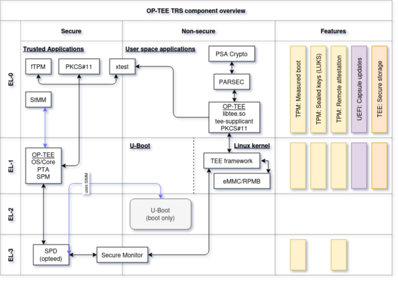
Note that this image is rather generic as depicted here. We have other areas
that could (and should) be added as well, for example SCMI, Xen,
FF-A, SwTPM to name a few. But perhaps it’s better to add them as
separate diagrams to avoid making the images too complex.
LUKS - Linux Unified Key Setup
Block devices, like filesystems and swap partitions, can be encrypted using the disk encryption system called LUKS. Conceptually, LUKS protects the data by leverage keyslots. Keyslots may include several kinds of keys, such as passphrases, OpenPGP public keys, or X.509 certificates. Encryption is carried out using a multi-layer technique. There are two versions of LUKS, with LUKS2 providing additional capabilities such robustness to header corruption and default use of the Argon2 encryption algorithm.
Xen
Xen is an open-source type-1 or baremetal hypervisor that allows multiple
instances of the same or different operating systems to run on a single
machine. It is used in various applications targeting different environments,
including server and desktop and embedded. The Xen Project hypervisor has a
small memory footprint, is independent of operating systems it is running,
it isolates drivers and it also supports paravirtualization, a technique, that
allows multiple operating systems to share system resources more efficiently.
Paravirtualization improves performance and reduces overhead by enabling direct
communication between the guest operating system and the hypervisor.
Xen manages CPU, memory, and interrupts while running directly on the hardware.
The VM’s runs on top of the hypervisor. A specialized and more privileged VM,
called Dom0, comprises system services, device drivers and software to manage a
Xen-based system. Alongside with that, there are usually other guests running
as VM’s as well, we refer to those as DomU. For more details about the Xen
project, please have a lot at the Xen Project.